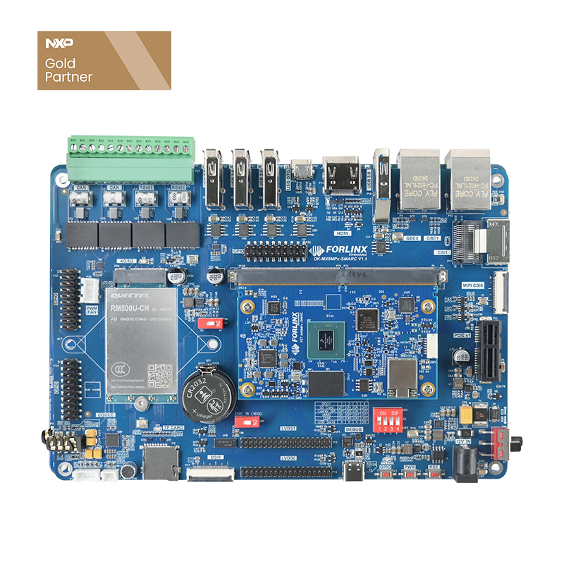
Máy tính nhúng OK-MX8MPQ-SMARC Single Board Computer SBC dựa trên IMX8M Plus Forlinx
Khoảng giá: từ 11.880.000₫ đến 12.450.000₫
| Số lượng | Giá |
|---|---|
| 11 - 19 | 11.583.000₫ |
| 20 - 49 | 11.345.400₫ |
| 50 - 99 | 11.226.600₫ |
| 100 - 1000 | 11.167.200₫ |
| 1001 - 10000 | 10.692.000₫ |
Datasheet ![]() Datasheet
Datasheet
Mã sản phẩm: SP25083012
| Model | 2GB+ 16GB, 4GB+32GB |
|---|
OK-MX8MPQ-SMARC Single Board Computer Based on NXP i.MX 8M Plus Processor
Product series: 8MPQ-SMARC
The OK-MX8MPQ-SMARC Single Board Computer is developed based on the NXP i.MX 8M Plus processor, which focuses on machine learning, vision, advanced multimedia and high-reliability industrial automation. It caters to applications such as smart cities, industrial IoT, smart healthcare and intelligent transportation.
OK-MX8MPQ-SMARC SBC

High-speed Communication Interface
4K Picture Quality and HiFi Voice Experience
HDMI interface supports up to 4K display output; it also features LVDS, MIPI-DSI display interface, the latest audio technology,
Cadence® Tensilica® HiFi 4 DSP @ 800 MHz, 18x I2S TDM, DSD512, S/PDIF Tx + Rx, 8-channel PDM microphone input, eARC, ASRC.
Advanced Multimedia Technology
3D/2D Graphic Acceleration
Machine Learning and Vision
Built-in NPU with 2.3 TOPS AI computing power to meet lightweight edge computing needs
Dual Image Signal Processor (ISP)
Product Application
▊ iMX8MP SMARC Video
Unboxing Forlinx Very First i.MX8M Plus SMARC Development Board
▊ Hardware Features
| FET-MX8MPQ-SMARC System on Module Basic Features | |
|---|---|
| CPU | NXP i.MX 8M Plus |
| Architecture | 4x Cortex-A53@1.6GHz + 1x Cortex-M7@800MHz |
| RAM | 2GB/4GB LPDDR4 |
| ROM | 16GB/32GB eMMC |
| Supply Voltage | DC 5V |
| Operating temp | -40℃~+85℃ |
| Connection | SMARC2.1, MXM3 Edge Connector(314 pins, 0.5mm pitch) |
| OS version | Linux 6.1.36 |
| Dimension | 82mm x 50mm |
| FET-MX8MPQ-SMARC System on Module Functional Parameters | ||
|---|---|---|
| Peripheral | NUM | Spec. |
| USB 3.0 | 2 | Contains 2 USB3.0/ 2.0 controllers integrated with PHY |
| USB 2.0 | 5 | Highspeed (HS), Full-speed (FS), and Low-speed (LS) |
| MIPI CSI | 2 | 2x 4-lane MIPI-CSI, up to 1.5 Gbps |
| MIPI DSI | 1 | 1x 4-lane MIPI-DSI, up to 1.5 Gbps
1080 p60 • WUXGA (1920×1200) at 60 Hz 1920×1440 at 60 Hz UWHD (2560×1080) at 60 Hz WQHD (2560×1440) by reduced blanking mode |
| LVDS | 2 | Up to 1920x1080p60 |
| HDMI | 1 | Up to 4kp30 |
| Ethernet | 2 | EMAC, 10/100/1000 Mbps, 1 is capable of TSN |
| PCIE x1 | 1 | PCI Express Gen 3 |
| CAN-FD | 2 | Complies with CAN 2.0B, ISO 11898-1 |
| SDIO | 1 | SDIO 3.0 |
| I2S | 2 | SAI, supports I2S, AC97, tdM and codec/DSP |
| SPI | 2 | Up to 52Mbit/s,master and slave are configurable |
| I2C | 5 | Up to 320kbps |
| UART | 4 | Up to 4Mbps |
| PWM | 3 | 16-bit timer |
| GPIO | >14 | General-purpose input/output (GPIO) modules with interrupt capability |
| WIFI & BT | 1 | WiFi 5 MIMO, Bluetooth 5.3, connected to processor by SDIO3.0 and UART |
| JTAG | 1 | IEEE 1149.1 testability (JTAG) |
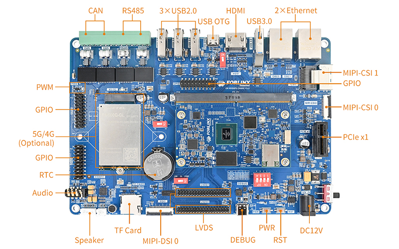
▊ OK-MX8MPQ-SMARC Carrier Board
 |
 |
| OK-MX8MPQ-SMARC Single Board Computer Features | |||
|---|---|---|---|
| Peripheral interfaces | NUM | Spec. | |
| USB 3.0 | 1 | USB Type A, only for HOST, with over-voltage and over-current protection; | |
| USB 2.0 | 3 | USB Type A, only for HOST, with over-voltage and over-current protection; | |
| USB 2.0 OTG | 1 | USB Type C, HOST / SLAVE switchable by DIP, with over-voltage and over-current protection; | |
| MIPI CSI | 2 | CSI1: daA3840-30mc-IMX8MP-EVK, 3840X2160;
CSI0: dual data lanes, by 26Pin FPC connector;OV5645 is well supported; Complies with SMARC, SBC can support DSI0 mode and LVDS0 mode controlled by Switch chip; 4-lane MIPI DSI by FPC connector; Fit with Forlinx 7” MIPI-DSI module with resolution of 1024 x 600@30fps; |
|
| LVDS | 2 | Complies with SMARC, SBC can support DSI0 mode and LVDS0 mode controlled by Switch chip;
Supports 2x 4-lane LVDS with 1080P, LVDS0 and DSI0 with shared data bit; Fit with Forlinx 10.1” LVDS module; |
|
| HDMI | 1 | HDMI 2.0a, up to 3840 x 2160@30fps; | |
| Ethernet | 2 | 10/100/1000Mbps adaptive, RJ45 connector, 1 supports TSN;
Carrier board is with PCIe X1 slot, complies with PCI Express Gen3; |
|
| TF Card | 1 | 1x SDIO, supports UHS-I TF card, up to 104MB/s; | |
| 4G/5G | 1 | Carrier board is preserved with M.2 B-KEY slot, 4G and 5G are alternative;
Recommended 4G model: EC20/ EC25;Recommended 5G module: RM500Q; On-board MicroSIM card slot; |
|
| I2S | 2 | 1x I2S connected to CODEC for audio;
1x I2S by pin headers for user’s expanding; |
|
| Audio | 1 | On-board NAU88C22YG, I2S;
Supports Phone and MIC, by 1x 3.5mm jack; Supports 2x 1W 8Ω speaker, by XH2.54 whiter header; |
|
| CAN FD | 2 | Industrial isolated CAN FD chip, up to 8Mbps;
Complies with CAN2.0B, by DG128 green header; |
|
| RS485 | 2 | Industrial isolated RS485, up to 4Mbps, by DG128 green header; | |
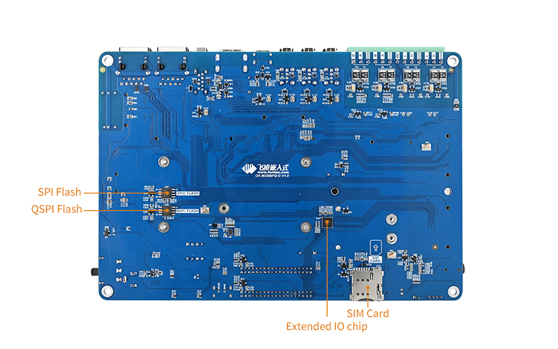
| QSPI | 1 | 2x 16MB FLASH, one based on QSPI; | |
| SPI | 1 | 2x 16MB FLASH, one based on SPI;
Can be configured to SPI booting mode; |
|
| RTC | 1 | Complies with SMARC, equipped with one CR2032 cell | |
| I2C | 4 | Can be mounted with audio, camera, TP and other related devices; | |
| Debug UART | 2 | 2 UARTs converted to 1 USB for debug device;
UART1 and UART2 on carrier board are used as Debug ports; |
|
| UART | 2 | UART0 and UART3 are used for RS485; | |
| PWM | 5 | For display backlight control and LED breathing; | |
| GPIO | By pin headers, contains some special functional pins defined according to SMARC standard; | ||
Sản phẩm tương tự