FET-MX8MPQ-SMARC System on Module SOM IMX8M Plus Forlinx
Khoảng giá: từ 7.170.000₫ đến 7.725.000₫
| Số lượng | Giá |
|---|---|
| 20 - 50 | 7.062.450₫ |
| 51 - 100 | 6.954.900₫ |
| 101 - 500 | 6.847.350₫ |
| 501 - 999 | 6.739.800₫ |
| 1000 + | 6.668.100₫ |
Datasheet ![]() Datasheet
Datasheet
Mã sản phẩm: SP25082861
| Model | 2GB+ 16GB, 4GB+32GB |
|---|
FET-MX8MPQ-SMARC System on Module Based on NXP i.MX 8M Plus Processor
Product series: 8MPQ-SMARC
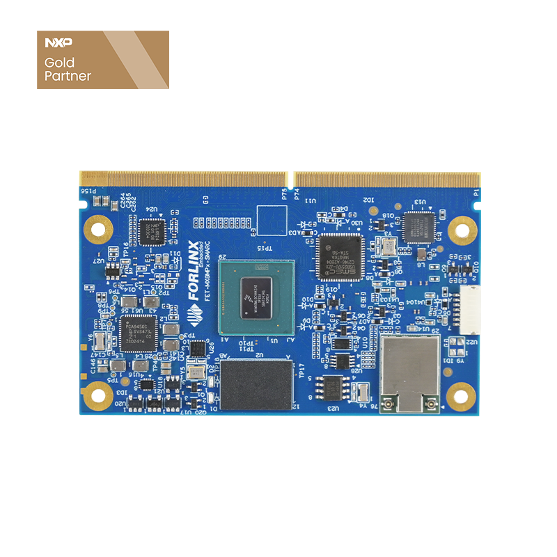
The FET-MX8MPQ-SMARC System on Module(SoM) / Computer on Module leverages the NXP i.MX 8M Plus Quad-Plus (4× Cortex-A53@1.6GHz + Cortex-M7@800 MHz) with a 2.3 TOPS NPU and ISP to deliver ML, vision and advanced multimedia in a high-reliability industrial platform. Built to the SMARC™ 2.1 standard (82 × 50 mm), it’s plug-and-play with all SMARC 1.x/2.x carriers. Rated for –40°C to +85°C on a single 5V supply, it thrives in harsh edge environments—ideal for smart cities, industrial IoT, smart healthcare and intelligent transportation.
NXP i.MX8M Plus Quad-Plus SMARC Module Key Advantages:
- Fully compliant with the SMARC 2.1 specification
- NXP i.MX 8M Plus application processor, 4× Cortex-A53 @ 1.6 GHz
- Cortex-M7 microcontroller core, up to 800 MHz
- 2.3 TOPS Neural Processing Unit (NPU) and hardware Image Signal Processor (ISP)
- Dual-band 2.4/5 GHz 2×2 Wi-Fi 5 (802.11ac) + Bluetooth 5.3
- Industry-leading build quality from Forlinx
- Preloaded Linux 6.1.36 LTS software stack with BSP, drivers, and sample code
FET-MX8MPQ-SMARC SoM

High-speed Communication Interface
4K Picture Quality and HiFi Voice Experience
HDMI interface supports up to 4K display output; it also features LVDS, MIPI-DSI display interface, the latest audio technology,
Cadence® Tensilica® HiFi 4 DSP @ 800 MHz, 18x I2S TDM, DSD512, S/PDIF Tx + Rx, 8-channel PDM microphone input, eARC, ASRC.
Advanced Multimedia Technology
3D/2D Graphic Acceleration
Machine Learning and Vision
Built-in NPU with 2.3 TOPS of AI computing power to meet lightweight edge computing needs
Dual Image Signal Processor (ISP)
Product Application
▊ iMX8MP SMARC Video
Unboxing Forlinx Very First i.MX8M Plus SMARC Development Board
▊ Hardware Features
|
|
| FET-MX8MPQ-SMARC System on Module Basic Features | |
|---|---|
| CPU | NXP i.MX 8M Plus |
| Architecture | 4x Cortex-A53@1.6GHz + 1x Cortex-M7@800MHz |
| RAM | 2GB/4GB LPDDR4 |
| ROM | 16GB/32GB eMMC |
| Supply Voltage | DC 5V |
| Operating temp | -40℃~+85℃ |
| Connection | SMARC2.1, MXM3 Edge Connector(314 pins, 0.5mm pitch) |
| OS version | Linux 6.1.36 |
| Dimension | 82mm x 50mm |
| FET-MX8MPQ-SMARC System on Module Functional Parameters | ||
|---|---|---|
| Peripheral | NUM | Spec. |
| USB 3.0 | 2 | Contains 2 USB3.0/ 2.0 controllers integrated with PHY |
| USB 2.0 | 5 | Highspeed (HS), Full-speed (FS), and Low-speed (LS) |
| MIPI CSI | 2 | 2x 4-lane MIPI-CSI, up to 1.5 Gbps |
| MIPI DSI | 1 | 1x 4-lane MIPI-DSI, up to 1.5 Gbps
1080 p60 • WUXGA (1920×1200) at 60 Hz 1920×1440 at 60 Hz UWHD (2560×1080) at 60 Hz WQHD (2560×1440) by reduced blanking mode |
| LVDS | 2 | Up to 1920x1080p60 |
| HDMI | 1 | Up to 4kp30 |
| Ethernet | 2 | EMAC, 10/100/1000 Mbps, 1 is capable of TSN |
| PCIE x1 | 1 | PCI Express Gen 3 |
| CAN-FD | 2 | Complies with CAN 2.0B, ISO 11898-1 |
| SDIO | 1 | SDIO 3.0 |
| I2S | 2 | SAI, supports I2S, AC97, tdM and codec/DSP |
| SPI | 2 | Up to 52Mbit/s,master and slave are configurable |
| I2C | 5 | Up to 320kbps |
| UART | 4 | Up to 4Mbps |
| PWM | 3 | 16-bit timer |
| GPIO | >14 | General-purpose input/output (GPIO) modules with interrupt capability |
| WIFI & BT | 1 | WiFi 5 MIMO, Bluetooth 5.3, connected to processor by SDIO3.0 and UART |
| JTAG | 1 | IEEE 1149.1 testability (JTAG) |
▊ Carrier Board
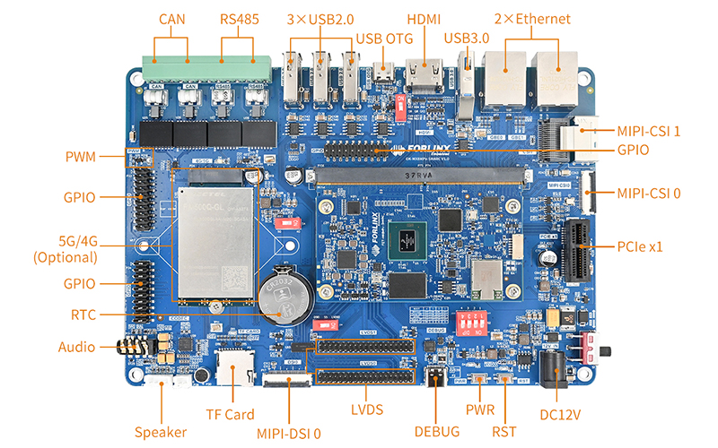
OK-MX8MPQ-SMARC Development Board
To minimize your development workload, we can provide starter kits that can be used as complete development platforms for evaluation and application development.
The OK-MX8MPQ-SMARC Single Board Computer from Forlinx is powered by the NXP i.MX 8M Plus processor, which features 4x Cortex-A53@1.6GHz + 1x Cortex-M7, 2GB/4GB LPDDR4 RAM, and 16GB/32GB eMMC ROM. With a split design and 314 pins, it offers seamless functionality and easy customization, and supports the Linux 6.1.36 system. With an open system architecture design, it can provide technical information for your secondary development.
| OK-MX8MPQ-SMARC Single Board Computer Features | |||
|---|---|---|---|
| Peripheral interfaces | NUM | Spec. | |
| USB 3.0 | 1 | USB Type A, only for HOST, with over-voltage and over-current protection; | |
| USB 2.0 | 3 | USB Type A, only for HOST, with over-voltage and over-current protection; | |
| USB 2.0 OTG | 1 | USB Type C, HOST / SLAVE switchable by DIP, with over-voltage and over-current protection; | |
| MIPI CSI | 2 | CSI1: daA3840-30mc-IMX8MP-EVK, 3840X2160;
CSI0: dual data lanes, by 26Pin FPC connector;OV5645 is well supported; Complies with SMARC, SBC can support DSI0 mode and LVDS0 mode controlled by Switch chip; 4-lane MIPI DSI by FPC connector; Fit with Forlinx 7” MIPI-DSI module with resolution of 1024 x 600@30fps; |
|
| LVDS | 2 | Complies with SMARC, SBC can support DSI0 mode and LVDS0 mode controlled by Switch chip;
Supports 2x 4-lane LVDS with 1080P, LVDS0 and DSI0 with shared data bit; Fit with Forlinx 10.1” LVDS module; |
|
| HDMI | 1 | HDMI 2.0a, up to 3840 x 2160@30fps; | |
| Ethernet | 2 | 10/100/1000Mbps adaptive, RJ45 connector, 1 supports TSN;
Carrier board is with PCIe X1 slot, complies with PCI Express Gen3; |
|
| TF Card | 1 | 1x SDIO, supports UHS-I TF card, up to 104MB/s; | |
| 4G/5G | 1 | Carrier board is preserved with M.2 B-KEY slot, 4G and 5G are alternative;
Recommended 4G model: EC20/ EC25;Recommended 5G module: RM500Q; On-board MicroSIM card slot; |
|
| I2S | 2 | 1x I2S connected to CODEC for audio;
1x I2S by pin headers for user’s expanding; |
|
| Audio | 1 | On-board NAU88C22YG, I2S;
Supports Phone and MIC, by 1x 3.5mm jack; Supports 2x 1W 8Ω speaker, by XH2.54 whiter header; |
|
| CAN FD | 2 | Industrial isolated CAN FD chip, up to 8Mbps;
Complies with CAN2.0B, by DG128 green header; |
|
| RS485 | 2 | Industrial isolated RS485, up to 4Mbps, by DG128 green header; | |
| QSPI | 1 | 2x 16MB FLASH, one based on QSPI; | |
| SPI | 1 | 2x 16MB FLASH, one based on SPI;
Can be configured to SPI booting mode; |
|
| RTC | 1 | Complies with SMARC, equipped with one CR2032 cell | |
| I2C | 4 | Can be mounted with audio, camera, TP and other related devices; | |
| Debug UART | 2 | 2 UARTs converted to 1 USB for debug device;
UART1 and UART2 on carrier board are used as Debug ports; |
|
| UART | 2 | UART0 and UART3 are used for RS485; | |
| PWM | 5 | For display backlight control and LED breathing; | |
| GPIO | By pin headers, contains some special functional pins defined according to SMARC standard; | ||
Sản phẩm tương tự